
Detection of color with Arduino and mobile Application
The detection of color is not an easy process, but there are elements that allow to get a bit of color that our eyes see, in this Arduino project I wanted to share a test of a color sensor reference TCS3200. Really what makes this sensor is to detect the intensity of light and convert it into a frequency and logically each color reflects a different intensity and therefore a different frequency.
Below I will describe certain characteristics that we consider when we use this color sensor. This is a low-cost sensor and not has high accuracy but is pretty close to what we want to detect and satisfactory results are obtained.
How is the detection of color with Arduino and a mobile application ?
The first thing to consider is the environmental factor, since because the color sensor detects light intensities is necessary to adjust this parameter best to not affect our measurement. I believe this was the main challenge in this project, and to adjust the brightness with white LEDs that come in the module is essential.
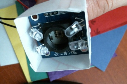 Is necessary that the LED light of color sensor point to the center of color to be detected, is important not to shine the center of sensor, you must also maximize the brightness and for that reason, in this Arduino project I did an enclosure around the sensor with white paper, in order to obtain as homogeneous brightness as possible over the surface to be detected.
If you look closely, you will see that the LEDs are around of plastic coating that brings the color sensor, if for some reason you let these LED light exceed the base that covers the detection zone, the color on the surface are not well detected.

It is important to consider this aspect, because otherwise the color may be detect it as very light or very dark, and even filters, Green and Blue would be a limit in which a green tone can be detected as blue.
For that reason you should adjust well the light so there is a good reflection on the surface of color.
The following is an schema of the circuit, this scheme not to describe the connection of the LCD but the project works without the LCD connected.
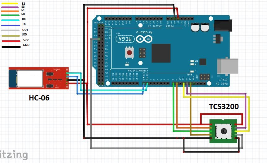
As shown in the circuit, the pin that reads the frequency is 47, this is recomended in ELECTRONIC PROJECTS page, where we can download the library FreqCount.h in the following LINK. Using pin 47 the frequency is more accurate because this pin is in the Digital port Arduino Mega, and FreqCount library requires an entry that have digital levels for operation.
Now basically the operation is to take readings every so often through the Arduino Mega on pin 47, and these readings depend on the configuration that we give to the pin S2 and S3 from the color sensor, which are what determine the filter with the which frequency sample is taken and the value of each of the filters that make up the RGB system is obtained. The S0 and S1 pins simply put on high level and LEDs that illuminate the surface is ever activated as well.
Here I share the LINK with Arduino code for this project, and then I share images of the blocks of programming mobile application on App Inventor.
3 blocks were designed to receive the color information of each filter through bluetooth module, then a separation between blocks with the timer was performed, the tone that each filter added to the final color we are reading is assigned, this tone is represented by a value of 0-255 for each filter and after of receive the information from each filter through bluetooth module, there colors are combined to show the resulting color on a canvas on mobile app.
To make it a little clearer I put the following example:
Suppose that we will perform the sequence to detect a dark yellow color, the first step is configure on Arduino Mega the Red filter and so the filter gives a value of 235, stores it in a variable and then sends it through the bluetooth module, then the Green filter is configured and this gives a value of 177, is stored in a variable and then sent via bluetooth, finally the Blue filter is configured and this gives a value of 5, is stored in a variable and is sent through the bluetooth module. Already from these three values collected in the application, are combined into a screen space of mobile phone called CANVAS which is given the three values of the filters and the canvas shows the resulting color.
The following video shows the operation of the mobile application communicating via Bluetooth with TCS3200 color sensor, connected to an Arduino Mega 2560.
The materials we’ve used in this Arduino project are:
Arduino Mega 2560
4×20 LCD
Bluetooth Module HC-06
Color Sensor TCS3200
Connection Cables
Hope you liked this little Arduino project, that surely will serve them to make their projects more and more complete, I thank you for visiting and even a next occasion.